Vickers Hardness Testing
The Vickers hardness test is suitable for a wide range of applications, including micro hardness testing. On this page, you can find a description of the Vickers hardness test, practical information on how to apply it and a list of our micro hardness testing machines for Vickers.

The Vickers hardness test at a glance:
- Ideal for micro hardness testing
- Can be used for case hardness depth measurement, coatings testing, welds and many others
- Standards: ASTM E384, ISO 6507 and JIS Z 2244.
About the Vickers hardness test
The Vickers hardness test is a versatile hardness test method, used for both macro and micro hardness testing. It has a broad load range, and is suitable for a wide range of applications and materials.
The Vickers hardness scale is often regarded as easier to use than other hardness methods: The process can be performed on a universal or micro hardness tester; the required calculations are independent of the size of the indenter; and the same indenter (a pyramidal diamond) can be used for all materials, irrespective of hardness.
The Vickers Hardness calculation
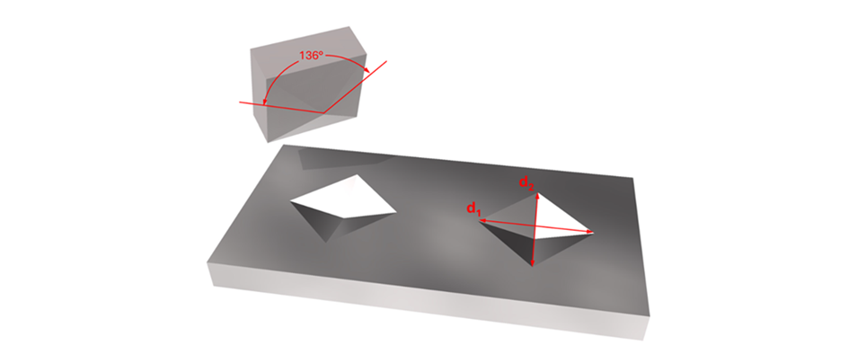
The Vickers Hardness (HV) is calculated by optically measuring the diagonal lengths of the impression left by the indenter. These measurements are than converted into a hardness value using a standard formula or reference table. Modern hardness testing instruments are equipped with integrated calculators that automatically compute and display the HV value.
HV = 1854.4 F/d^2
HV: Vickers hardness
F: Test load (gf)
d: Average diagonal length (µm)
- Load range: From 1 gf up to 100 kgf
Vickers Loads
| Standard | Load range | |
|
ISO 6507 |
1 gf - 100 kgf or more |
(0.0098 - 9.807 N) |
|
ASTM E384 |
1 gf - ≤1 kgf |
(0.0098 - ≤9.807 N) |
- Indentation time: 10-15 seconds
- Sample thickness ASTM: At least 10 times the indentation depth
- Sample thickness ISO: At least 1.5 times the diagonal length.

How to measure Vickers Hardness in 6 steps
Using a DuraVista-80 hardness testing machine with motorized stage:
- Place your sample on the stage.
- Click and drag the mouse to move the sample into position.
- Press autofocus or scroll to focus.
- Select the test load.
- Choose a measurement objective.
- Start the test.
Indent spacing
Regardless of the micro hardness tester you use, when you perform a Vickers hardness test, your indentation will deform the surrounding material and alter its properties. In order to avoid misinterpretations of perceived hardness, the Vickers hardness testing standards prescribe a certain distance between multiple indentations.
Steel and copper
- At least 3 diagonal widths between indentations
Lead, zinc and aluminum
- At least 6 diagonal widths between indentations

Diagonal widths
To ensure accurate reading of the indents, the Vickers hardness testing standards prescribe a minimum diagonal width of 20 µm.
For instance, this implies that CHD (see below) measurements using less than HV0.2 should generally be avoided, as they will produce indents smaller than 20 µm.
Prepare for a Vickers hardness test
Specimen
Before placing a sample on the micro hardness testing machine, ensure that the surface is properly prepared. The required surface finish depends on the test load being applied.
Macrohardness testing (loads > 1 kgf)
- The test surface should be ground to provide a smooth, uniform finish.
Microhardness testing (loads ≤ 1 kgf)
- The test surface should be mechanically polished or electropolished to ensure accurate measurement of the small indentation.
Proper surface preparation is essential for obtaining reliable and repeatable Vickers hardness results.
Equipment
To ensure reliable and traceable results, the Vickers hardness tester should undergo direct verification and calibration at least annually by an accredited calibration laboratory. In-between direct calibrations, operators are encouraged to perform regular indirect verifications using certified reference test blocks with known hardness values.
Environment
Among all hardness testing methods, the Vickers test is the most sensitive to shock and vibration, particularly when performing microhardness measurements. To ensure accurate and repeatable results, the instrument should be installed on a stable, rigid surface. Vibrations from nearby machinery, foot traffic, or other external sources should be minimized or eliminated whenever possible.
ISO and ASTM standards specify an operating temperature between 10 °C and 35 °C.
Operator
The operator is responsible for ensuring that the specimen is correctly positioned and remains stable throughout the complete test cycle. To prevent measurement errors caused by material deformation, indentations should be spaced sufficiently apart and away from the specimen edges.
As a general guideline:
- The distance between the centers of two adjacent indentations should be at least 3 times the diagonal length (3d) for steel and copper alloys.
- For light metals, the spacing should be at least 6 times the diagonal length (6d).
- The distance between an indentation and the edge of the test piece should be 2.5d to 3d, where d is the average identation diagonal length.
For specific applications, always consult the relevant Vickers testing standard to confirm the required spacing and testing conditions.
Vickers test methods and applications
Below you can see an overview of the Vickers hardness test methods and the most common applications:
| Test Method | Application / Material |
|
HV0.01 |
Small Geometrics, Thin Layers, Ceramics |
|
HV0.1 |
Hardness Progressions, CHD/Eht-Nht-RHt |
|
HV1 |
Hardness Progressions, CHD/Eht-Nht-RHt |
|
HV5 |
Welding Test, Sintered Metals |
|
HV30 |
Jominy Test, Surface Hardness Testing |
Case Hardness Depth (CHD) Measurement
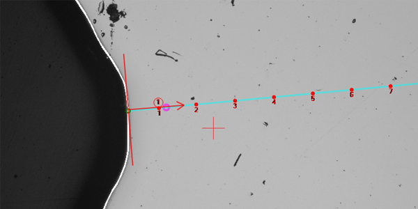
Hardness testing, especially the Vickers method, is widely used to determine the hardness distribution and effective case depth of surface-hardened steels. This is done by making a series of hardness indents from the edge of the cross-sectioned sample towards the center. The hardness progression is plotted in a graph and the distance from the surface to the hardness limit is calculated.
- Case depth = Distance from surface to hardness limit

Hardness Depth Methods
Different hardening processes produce different hardness characteristics, and therefore different methods are used to determine hardness depth. The appropriate evaluation procedure depends on the hardening process applied. The most used hardness depth calculation methods are:
For carburized or carbonitrided parts (EN ISO 18203)
Hardness limit = 550 HV
CHD (Eht) = Distance from the surface to the point where the hardness is 550 HV
For induction or flame-hardened parts (EN ISO 18203)
Hardness limit = 80% x (minimum) surface hardness
CHD (Rht) = Distance from the surface to the point where hardness is 80% of the (minimum) surface hardness
For Nitrided parts (EN ISO 18203 & DIN 50190-3)
Hardness limit = Core hardness + 50 HV
CHD (Nht, NCD) = (Maximum) distance from the surface to the point where hardness is 50 HV above core hardness

Hardness testing of welds
Hardness testing of welds is a subgroup of the Vickers hardness test. The purpose of these hardness tests is to evaluate the strength of the weld, with particular focus on hardness around the heat-affected zone (HAZ). This is because the hardness in and around the HAZ can help evaluate the brittleness of the weld and can therefore help you determine whether or not the weld has the strength you require. Hardness testing of welds can be performed on any Vickers micro hardness testing machine.
When hardness testing of welds, a series of measurements are made in a given pattern at a specific distance from the sample edge or top of the weld. The progression of the hardness values can then be plotted in a graph.
- Methods typically used: HV5 and HV10
- Applicable standards: ISO 9015-1/-2
Hardness Mapping
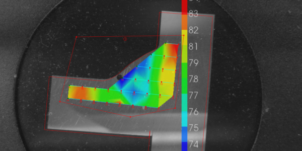
Hardness mapping provides a detailed visualization of hardness distribution across a material’s surface or cross-section. By recording hundreds or even thousands of individual hardness values over a defined area, intuitive color maps can be generated to clearly visualize hardness distribution and identify variations across the sample.
This enables users to quickly identify hardness variations, gradients, and critical zones that may not be visible with individual hardness measurements alone. Hardness mapping is particularly valuable for the analysis of heat-treated materials, welds, and components under investigation for failure or damage.
Knoop versus Vickers method
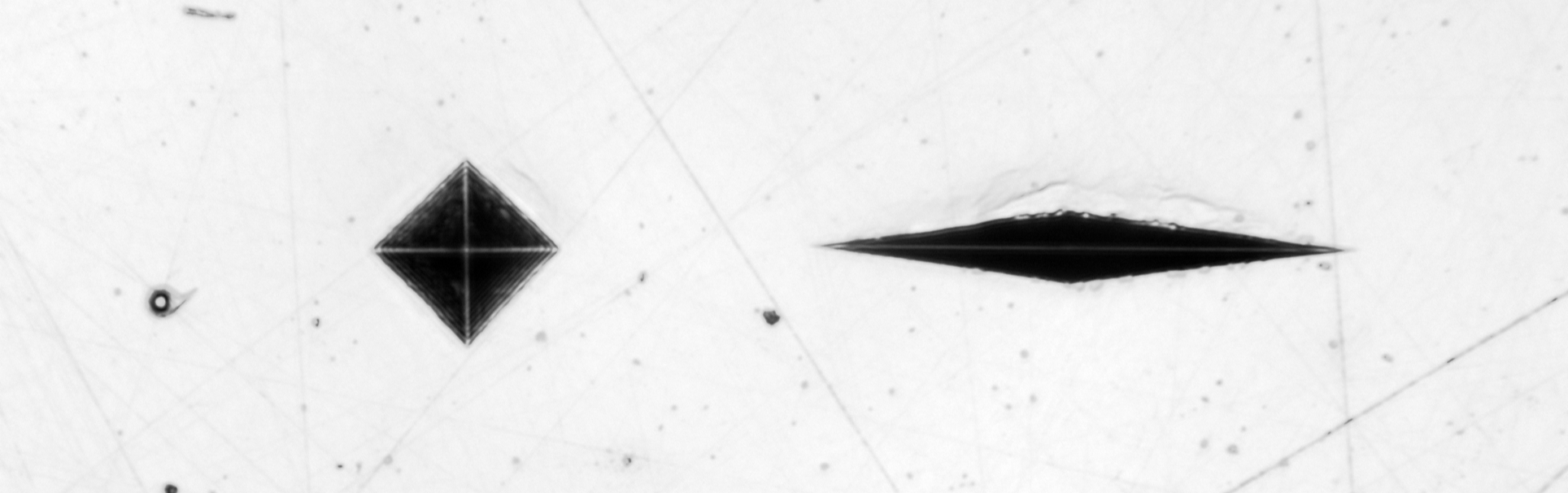
In most cases, the Vickers hardness test is used to determine hardness in materials in the micro hardness test load range. However, in some cases the Vickers method has some constrains where the Vickers indents sizes is a poor fit. For many of those cases the Knoop hardness test is often a solution, for example for coatings, or to overcome the problem of cracking in brittle materials.
| Vickers (HV) | Knoop (HK) | |
| Standards | ISO 6507, ASTM E384 | ISO 4545, ASTM E384 |
| Indenter geometry | Symmetrical diamond pyramid 136º | Elongated diamond pyramid 172º |
| Indent shape | Square-shaped | Rhombic, long and narrow |
| Diagonal measurement | 2 diagonals | 1 diagonal |
| Indent depth | 1/30 of diagonal length | 1/7 of diagonal length |
| Main application | Universal method with broad acceptance and wide load range, Industry standard for CHD, NHD, and SHD measurements, Welds | Thin coatings and brittle materials (Ceramics) |
| Limitations | Smaller diagonals at low loads can increase measurement uncertainty. | Less commonly specified in industry standards and specifications. |
Explore our Vickers Hardness Testers for Labs
Vickers hardness testing is the preferred choice for precise hardness measurements on small, thin, or delicate components. The Vickers scale delivers highly accurate and repeatable results across diverse materials, making it ideal for quality control, research, and advanced material characterization.
Whether you need microhardness testing for surface layers and coatings or standard Vickers testing for metals and alloys, our large range of Vickers hardness testers offers reliable performance and exceptional measurement accuracy.
Downloads & Webinars about Hardness Testing
Whether you're just starting with hardness testing or are an experienced professional, this curated selection of resources is here to assist you in your work.
Take advantage of downloadable reference posters for easy use in your lab, and dive into expert-led webinars hosted by our application specialists to deepen your understanding of hardness testing techniques and methods.

Hardness testing posters
At present we have three different posters about hardness testing – all suitable for any lab. Download all posters now. Hardness Conversion Hardness Comparison Metallic materials
Hardness Conversion
Hardness Comparison
Metallic materials

Webinars about hardness testing
Upgrade your preparation skills and watch our recorded webinars with our application specialists about hardness testing.
Visual Analysis Inspection & Maintenance
Newest Generation of Hardness Testers
Sample Preparation and Parameters Influencing Results